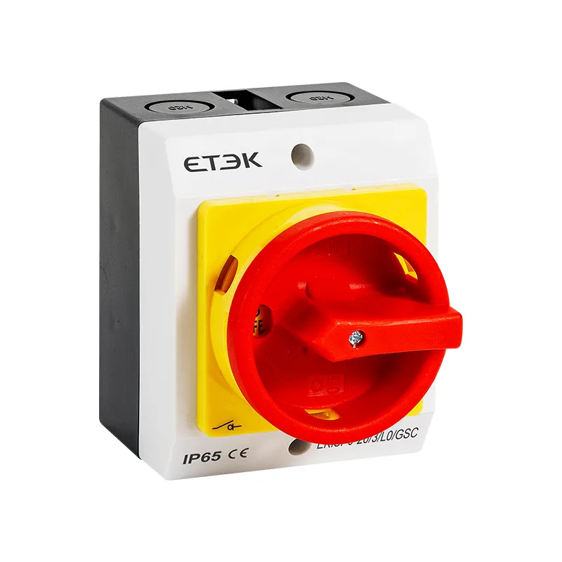
Model: EKISP
IP65 Weatherproof AC Isolator Switch
Inquire

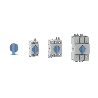
| EKD80 - | PM | 80 | R① | -3 | RY② |
| Type of Switch- disconnectors |
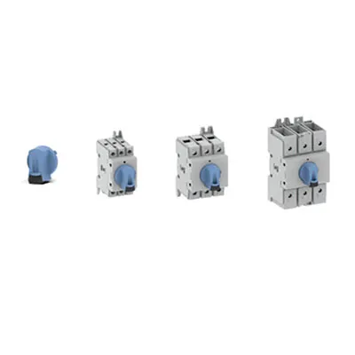
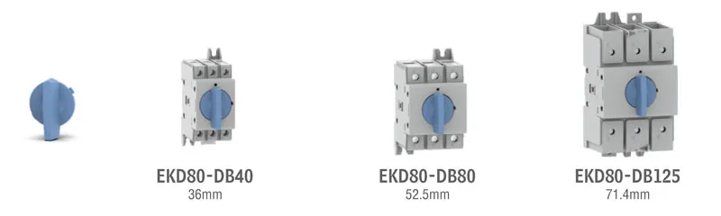
installation Form DB Rail installation PM Panel mounting DC Door lock installation EL External plastic boxes ELA External aluminum box |
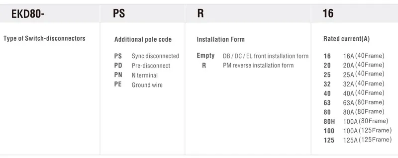
Rated current(A) 16 16A (40 Frame) 20 20A (40 Frame) 25 25A (40 Frame) 32 32A (40 Frame) 40 40A (40 Frame) 63 63A (80 Frame) 80 80A (80 Frame) 80H 100A (80 Frame) 100 100A (125 Frame) 125 125A (125 Frame) |
Lock form Empty Without lock R With lock |
Poles 2 2P 3 3P 4 4P 5 5P 6 6P 7 7P 8 8P |
Handel Option RY Rotating red/yellow handle With lock only BW Black/white rotating handle Optional with lock/without lock BB Black/black rotating handle Only without lock |
①Not suitable for EL external plastic box /ELA external aluminum box
②Not suitable for DB rail installation / EL external plastic box/ELA external aluminum box
|
|
|||||
|
01 |
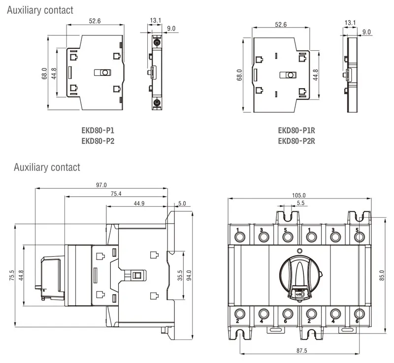
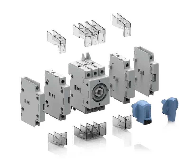
Add-on Auxiliary Contacts |
02 |
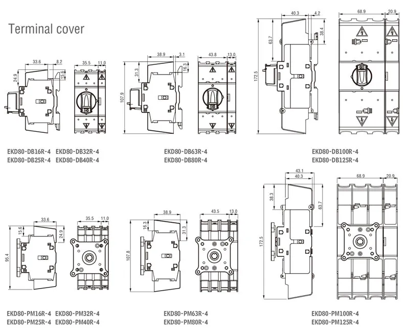
Terminal cover |
03 |
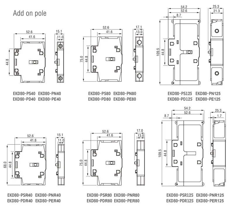
Side Mount Add-on Fourth Pole |
|
The isolating switch adopts the same auxiliary contact, and the auxiliary contact and the main pole of the switch acts at the same time. A normally open contact with PR disconnects function can be provided as required. The isolation switch can be installed with up to four auxiliary accessories (About 2 and 2 on the left) |
The isolation switch terminal cover has a simple |
Simultaneous or early contact operation |
|||
|
04 |
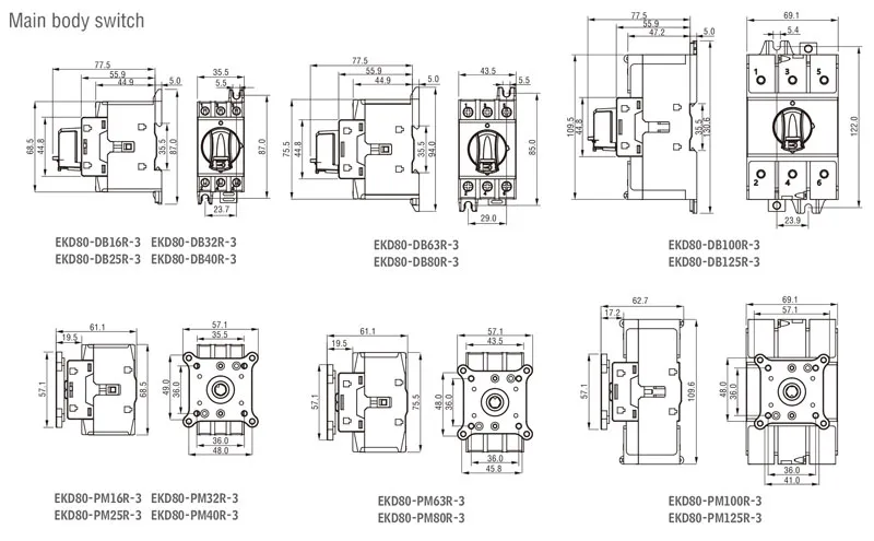
Switch body |
05 |
Rotating Handle Parts |
|
|
|
The switch adopts compression contact |
The isolation switch terminal cover has a simple appearance design, high-quality transparent PC material, flame-retardant, high strength, no color change after long-term use, high-quality waterproof and easy to install. |
|
|||
|
Type |
3P |
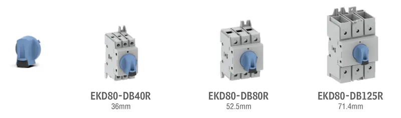
EKD80- DB16R -3 |
EKD80- DB20R -3 |
EKD80- DB25R -3 |
EKD80- DB32R -3 |
EKD80- DB40R -3 |
EKD80- DB63R -3 |
EKD80- DB80R -3 |
EKD80- DB80HR -3 |
EKD80- DB100R -3 |
EKD80- DB125R -3 |
|
|
4P |
EKD80- DB16R -4 |
EKD80- DB20R -4 |
EKD80- DB25R -4 |
EKD80- DB32R -4 |
EKD80- DB40R -4 |
EKD80- DB63R -4 |
EKD80- DB80R -4 |
EKD80- DB80HR -4 |
EKD80- DB100R -4 |
EKD80- DB125R -4 |
||
|
Current Agreed heating current (≤40°C) |
16A |
20A |
25A |
32A |
40A |
63A |
80A |
100A |
100A |
125A |
||
|
IEC rated operational current le AC-21 A/B (≤690V) |
16A/16A |
20A/20A |
25A/25A |
32A/32A |
40A/40A |
63A/63A |
80A/80A |
100A/100A |
100A/100A |
125A/125A |
||
|
lEC rated |
415V |
16A/16A |
20A/20A |
25A/25A |
32A/32A |
40A/40A |
63A/63A |
80A/80A |
100A/100A |
100A/100A |
125A/125A |
|
|
500V |
||||||||||||
|
690V |
32A/40A |
40A/63A |
63A/80A |
63A/80A |
80A/100A |
100A/125A |
||||||
|
IEC rated |
415V |
16A/16A |
20A/20A |
25A/25A |
32A/32A |
40A/40A |
63A/63A |
80A/80A |
80A/80A |
100A/100A |
125A/125A |
|
|
500V |
25A/25A |
|
63A/63A |
|
80A/100A |
100A/125A |
||||||
|
690V |
|
40A/40A |
|
63A/63A |
63A/63A |
|||||||
|
lEC rated |
110VDC |
16A① |
20A① |
25A① |
32A① |
40A① |
63A① |
80A① |
80A① |
100A① |
125A① |
|
|
250VDC |
16A② |
20A② |
25A② |
32A② |
40A② |
63A② |
80A② |
80A② |
100A② |
125A② |
||
|
400VDC |
16A③ |
20A③ |
25A③ |
25A③ |
40A③ |
63A③ |
||||||
|
lEC rated |
415V |
7.5KW |
9KW |
11KW |
15KW |
18.5KW |
30KW |
37KW |
45KW |
55KW |
||
|
500V |
||||||||||||
|
690V |
11KW |
15KW |
||||||||||
|
Short circuit withstand current of fuse protection (kA rms expected value) |
||||||||||||
|
Fuse class |
415V |
16A |
20A |
25A |
32A |
40A |
63A |
80A |
100A |
125A |
||
|
Rated conditional short-circuit current |
415V |
50kA |
25kA |
|||||||||
|
Short circuit withstand current of circuit breaker for protection, any circuit breaker that can trip within 0.3s |
||||||||||||
|
Rated short-time withstand current |
0.3S |
2.5kA |
3kA |
5kA |
||||||||
|
Short circuit performance (unprotected) |
||||||||||||
|
Rated short-time withstand current |
1S |
1.26kA |
1.5kA |
2.75kA |
||||||||
|
Rated short circuit making capacity |
1.8kA |
2.1kA |
3.9kA |
|||||||||
|
Cross area of terminals |
1.5~16mm2 |
2.5~35mm2 |
10~70mm2 |
|||||||||
|
Rated insulation voltage Ui |
800V |
|||||||||||
|
Rated impulse withstand voltage Uimp |
8kV |
|||||||||||
|
Mechanical Endurance |
100000 |
|||||||||||
|
Ambient Temperature |
Operating -25...+55℃ Storage -40...+70°C |
|||||||||||
①Each pole is used as positive and negative
②Three poles are used in series with positive and negative poles, of which two poles are in series, and the other is negative
③four poles are used in series with positive and negative poles
|
Type |
3P |
EKD80 -DB16 -3 |
EKD80 -DB20 -3 |
EKD80 -DB25 -3 |
EKD80 -DB32 -3 |
EKD80 -DB40 -3 |
EKD80 -DB63 -3 |
EKD80 -DB80 -3 |
EKD80 -DB80H -3 |
EKD80 -DB100 -3 |
EKD80 -DB125 -3 |
|
|
4P |
EKD80 -DB16 -4 |
EKD80 -DB20 -4 |
EKD80 -DB25 -4 |
EKD80 -DB32 -4 |
EKD80 -DB40 -4 |
EKD80 -DB63 -4 |
EKD80 -DB80 -4 |
EKD80 -DB80H -4 |
EKD80 -DB100 -4 |
EKD80 -DB125 -4 |
||
|
Current Agreed heating current (≤40°C) |
16A |
20A |
25A |
32A |
40A |
63A |
80A |
100A |
100A |
125A |
||
|
IEC rated operational current le AC-21 A/B (≤690V) |
16A/16A |
20A/20A |
25A/25A |
32A/32A |
40A/40A |
63A/63A |
80A/80A |
100A/100A |
100A/100A |
125A/125A |
||
|
lEC rated |
415V |
16A/16A |
20A/20A |
25A/25A |
32A/32A |
40A/40A |
63A/63A |
80A/80A |
100A/100A |
100A/100A |
125A/125A |
|
|
500V |
||||||||||||
|
690V |
32A/40A |
40A/63A |
63A/80A |
63A/80A |
80A/100A |
100A/125A |
||||||
|
IEC rated |
415V |
16A/16A |
20A/20A |
25A/25A |
32A/32A |
40A/40A |
63A/63A |
80A/80A |
80A/80A |
100A/100A |
125A/125A |
|
|
500V |
25A/25A |
|
63A/63A |
|
80A/100A |
100A/125A |
||||||
|
690V |
|
40A/40A |
|
63A/63A |
63A/63A |
|||||||
|
lEC rated |
110VDC |
16A① |
20A① |
25A① |
32A① |
40A① |
63A① |
80A① |
80A① |
100A① |
125A① |
|
|
250VDC |
16A② |
20A② |
25A② |
32A② |
40A② |
63A② |
80A② |
80A② |
100A② |
125A② |
||
|
400VDC |
16A③ |
20A③ |
25A③ |
25A③ |
40A③ |
63A③ |
||||||
|
lEC rated |
415V |
7.5KW |
9KW |
11KW |
15KW |
18.5KW |
30KW |
37KW |
45KW |
55KW |
||
|
500V |
||||||||||||
|
690V |
11KW |
15KW |
||||||||||
|
Short circuit withstand current of fuse protection (kA rms expected value) |
||||||||||||
|
Fuse class |
415V |
16A |
20A |
25A |
32A |
40A |
63A |
80A |
100A |
125A |
||
|
Rated conditional short-circuit current |
415V |
50kA |
25kA |
|||||||||
|
Short circuit withstand current of circuit breaker for protection, any circuit breaker that can trip within 0.3s |
||||||||||||
|
Rated short-time withstand current |
0.3S |
2.5kA |
3kA |
5kA |
||||||||
|
Short circuit performance (unprotected) |
||||||||||||
|
Rated short-time withstand current |
1S |
1.26kA |
1.5kA |
2.75kA |
||||||||
|
Rated short circuit making capacity |
1.8kA |
2.1kA |
3.9kA |
|||||||||
|
Cross area of terminals |
1.5~16mm2 |
2.5~35mm2 |
10~70mm2 |
|||||||||
|
Rated insulation voltage Ui |
800V |
|||||||||||
|
Rated impulse withstand voltage Uimp |
8kV |
|||||||||||
|
Mechanical Endurance |
100000 |
|||||||||||
|
Ambient Temperature |
Operating -25...+55℃ Storage -40...+70°C |
|||||||||||
①Each pole is used as positive and negative
②Three poles are used in series with positive and negative poles, of which two poles are in series, and the other is negative
③four poles are used in series with positive and negative poles