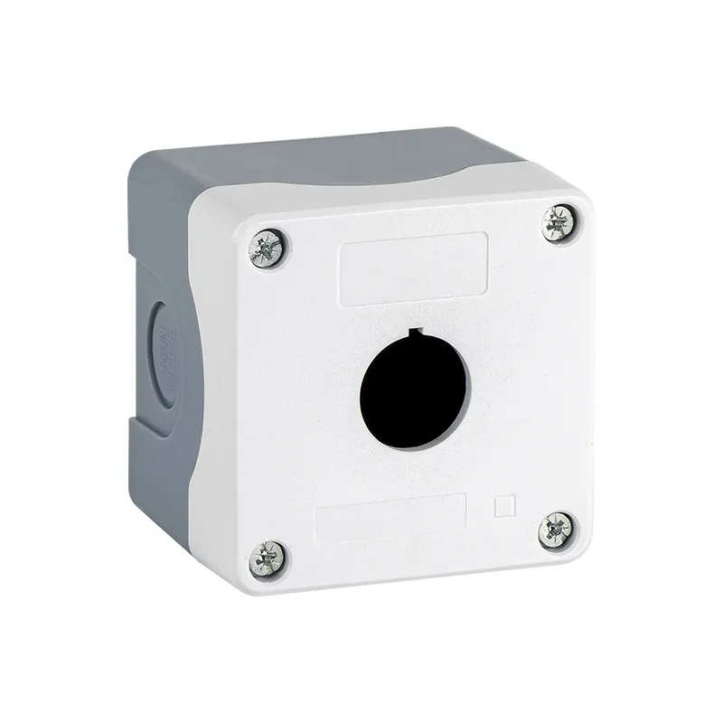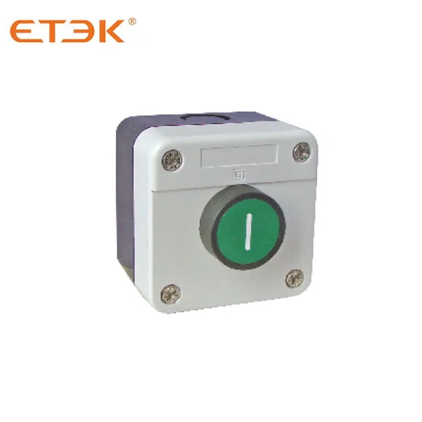
Model: EKCB
Push Button Station Enclosure ∅22mm IP65
Inquire

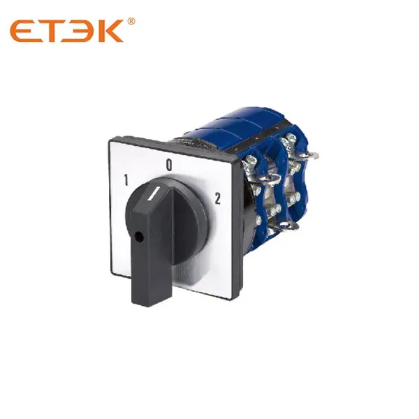
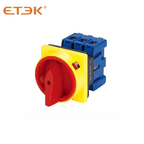
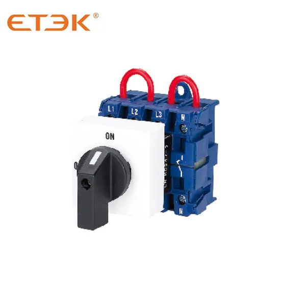
The EKRS sereies rotary switch mainly applies to 440V and below,AC 50Hz or 240V and below DC circuits. For breaking and closing, change-over of circuits unfrequently manual operation. And the typical application are: control switch of 3 phase motors, control switch of switch gear, control switch of instruments,and change-over switch of machinery and welding machine.
● The series comply with the IEC 60947-3,IEC 60947-5-1.
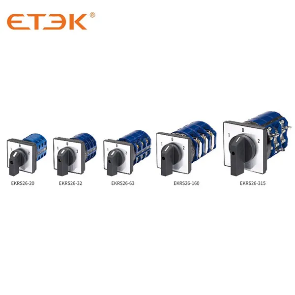
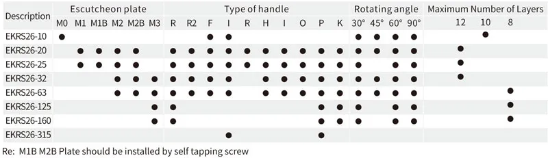
● The EKRS26 series have 8 current ratings: 10A,20A,25A,32A,63A,125A ,160A and 315A.
● The EKRS26 series rotary switch were designed for multiple functions, wide variety of applications.
● The EKRS26-10,EKRS26-20,EKRS26-25,and EKRS26-32F have finger protection terminals.
● Both of them are applicable in circuits when an physical control is required.
● We can equip protective box for 20A,25A,32A and 63A.
● Ambient temperature does not exceed 40℃, and the average temperature, measured over a period of 24 hours, do not exceed 35℃
● Ambient temperature should not be below -25℃
● Should Not be installed over 2000m above sea level
● The humidity should not exceed 50% when the ambient temperature is 40℃ and higher humidity is allowed for lower temperature
● A clean environment is required
● Please follow our manual
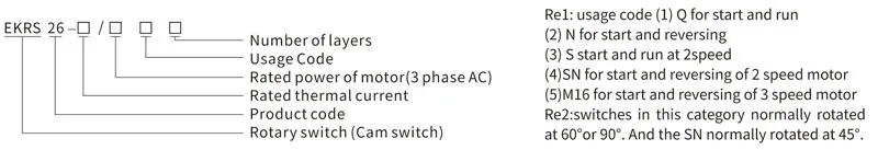
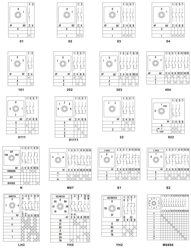
Use as control switches
Use as motor switches
Use as control switch for a main circuit
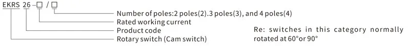
● Change-over switch
● Motor switch
● Control switch
● Limied movement
● Spring return
● Limited movement with spring return
● Switches with limited movement could have 12 layers in maximum (for 32 A and below). And for 63 A and above could have 8 layers in maximum
● Switches with spring return could have 3 layers in maximum
● Motor switches could have 6 layers in maximum
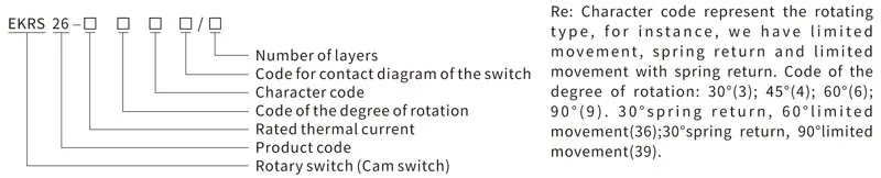
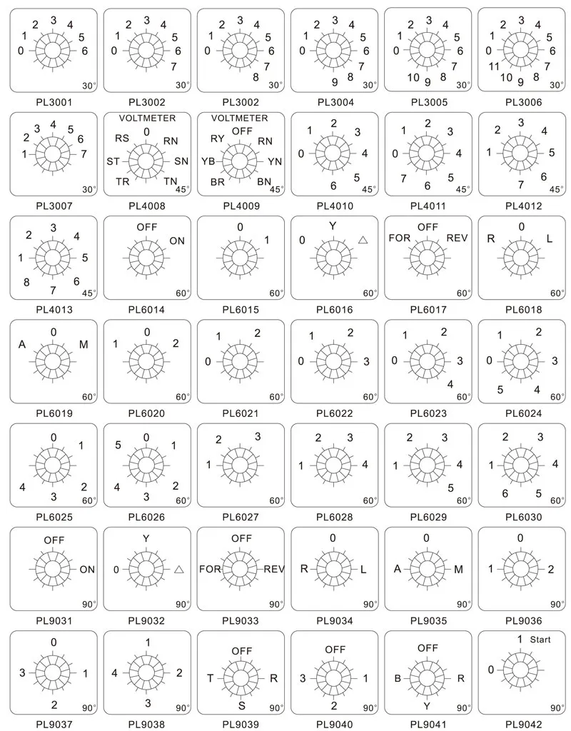
| Operation angle |
Character code |
Position of handle | |||
| 30° Rotation | 45° Rotation | 60° Rotation | 90° Rotation | ||
| Spring retuen |
A | 0° ← 30° | 0° ← 45° | 0° ← 60° | 0° ← 90° |
| B | 30° → 0° ← 30° | 45° → 0° ← 45° | 60° → 0° ← 60° | 90° → 0° ← 90° | |
| X | 60° → 30° → 0° ← 30° ← 60° | 90° → 45° → 0° ← 45° ← 90° | |||
| Y | 90° → 60° → 30° → 0° ← 30° ← 60° ← 90° | ||||
| Limited movement |
C | 0° 30° | 0° 45° | 0° 60° | |
| D | 30° 0° 30° | 45° 0° 45° | 60° 0° 60° | ||
| E | 30° 0° 30° 60° | 45° 0° 45° 90° | 60° 0° 60° 120° | ||
| F | 60° 30° 0° 30° 60° | 90° 45° 0° 45° 90° | 60° 0° 60° 120° | ||
| G | 60° 30° 0° 30° 60° 90° | 90° 45° 0° 45° 90° 135° | 120° 60° 0° 60° 120° 180° | ||
| H | 90° 60° 30° 0° 30° 60° 90° | 135° 90° 45° 0° 45° 90° 135° | |||
| I | 90° 60° 30° 0° 30° 60° 90° 120° | 135° 90° 45° 0° 45° 90° 135° 180° | |||
| J | 120° 90° 60° 30° 0° 30° 60° 90° 120° | ||||
| K | 20° 90° 60° 30° 0° 30° 60° 90° 120° 150° | ||||
| L | 150° 120° 90° 60° 30° 0° 30° 60° 90° 120° 150° | ||||
| M | 150° 120° 90° 60° 30° 0° 30° 60° 90° 120° 150° 180° | ||||
| N | 45° 45° | 30° 30° | |||
| P | 90° 0° 90° | ||||
| T | 0° 90° | ||||
| V | 90° 0° | ||||
| Limited movement with spring return |
R | 30° 0° ← 30° | 270° 0° 90° 180° | ||
| Q | 30° → 0° 60° | 135° 90° 45° 0° ← 45° | |||
| S | 135° 90° 45° 0° ← 45° | ||||
| W | 30° → 90° 0° ← 30° | 90° → 45° 0° 45° ← 90° | |||
Mechanical life without load: 0.1×10⁶ times, operation frequency is 120 times/h.
Mechanical life with load: 0.03×10⁶ times, operation frequency is 120 times/h.
| Description | EKRS 26-10 |
EKRS 26-20 |
EKRS 26-25 |
EKRS 26-32 |
EKRS 2626-63 |
EKRS 26-125 |
EKRS 26-160 |
EKRS 26-315 |
||||||||||
| Rated insulation voltage | Ui | V | 660 | 660 | 660 | 660 | 660 | 660 | 660 | 660 | ||||||||
| Rated thermal current | Ith | A | 10 | 20 | 25 | 32 | 63 | 125 | 160 | 315 | ||||||||
| Rated working voltage | Ue | V | 240 | 440 | 240 | 440 | 240 | 440 | 240 | 440 | 240 | 440 | 240 | 440 | 240 | 440 | 240 | 440 |
| Rated working current Ie | ||||||||||||||||||
| AC-21A, AC-22A | A | 10 | 10 | 20 | 20 | 25 | 25 | 32 | 32 | 63 | 63 | 100 | 100 | 150 | 150 | 315 | 315 | |
| AC-23A | A | 7.5 | 7.5 | 15 | 15 | 22 | 22 | 30 | 30 | 57 | 57 | 90 | 90 | 135 | 135 | 265 | 265 | |
| AC-2 | A | 7.5 | 7.5 | 15 | 15 | 22 | 22 | 30 | 30 | 57 | 57 | 90 | 90 | 135 | 135 | 265 | 265 | |
| AC-3 | A | 5.5 | 5.5 | 11 | 11 | 15 | 15 | 22 | 22 | 36 | 36 | 75 | 75 | 95 | 95 | 110 | 110 | |
| AC-4 | A | 1.75 | 1.75 | 3.5 | 3.5 | 6.5 | 6.5 | 11 | 11 | 15 | 15 | 30 | 30 | 55 | 55 | 95 | 95 | |
| AC-15 | A | 2.5 | 1.5 | 5 | 4 | 8 | 5 | 14 | 6 | |||||||||
| AC-13 | A | 0.4 | 0.5 | |||||||||||||||
| Power | ||||||||||||||||||
| AC-23A | KW | 1.8 | 3 | 3.7/ 2.5 |
7.5/ 3.7 |
5.5 /3 |
11/ 5.5 |
7.5 /4 |
1.5/ 7.5 |
15 /10 |
30/ 18.5 |
30/ 15 |
45/ 22 |
37/ 22 |
75/ 37 |
75/ 37 |
132 /55 |
|
| AC-2 KW | KW | 2.5 | 3.7 | 4 | 7.5 | 5.5 | 11 | 7.5 | 15 | 18.5 | 30 | 30 | 45 | 37 | 55 | 55 | 95 | |
| AC-3 KW | KW | 1.5 | 2.2 |
3/ |
5.5/3 | 4/3 |
7.5 |
5.5 |
11/ |
11 |
18.5 /11 |
15/ 7.5 |
30 /13 |
22 /11 |
37/ 18.5 |
27 /22 |
55 /30 |
|
| AC-4 KW | KW | 0.37 | 0.55 |
0.55/ |
1.5/ |
1.5 |
3/ |
2.7 |
5.5 |
5.5 |
7.5 /4 |
6/3 | 12/ 5.5 |
10 /4 |
15/ 7.5 |
15/ 7.5 |
25 /11 |
|
Re1: Neutral
Re2: The power under:
AC-23A、AC-3、AC-4 are in three phase three pole, and the denominator represents the power under single phase two poles

Square Escutcheon Plate and Rectangular Escutcheon Plate

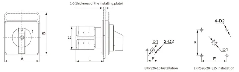

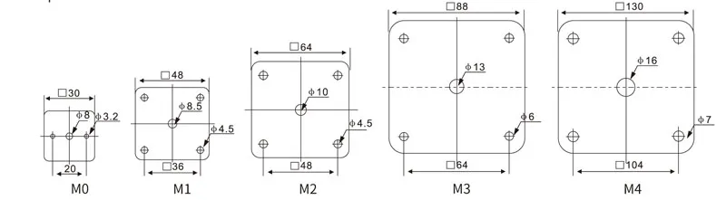
| Description | Escutcheon plate | Dimensions(mm) | Installation(mm) | ||||||
| A | B | C | L | E | F | D1 | D2 | ||
| EKRS26-10 | M0 square | 30 | 30 | 28 | 22+8n | 20 | φ8 | φ3.2 | |
| EKRS26-20 | M1 square | 48 | 48 | 43 | 22+9.6n | 36 | 36 | φ8.5 | φ4.5 |
| M1 rectangular | 48 | 60 | 43 | 22+9.6n | 36 | 36 | φ8.5 | φ4.5 | |
| M2 square | 64 | 64 | 43 | 25+9.6n | 48 | 48 | φ10 φ10 | φ4.5 φ4.5 | |
| M2 rectangular | 64 | 80 | 34 | 25+9.6n | 48 | 48 | |||
| EKRS26-25 | M1 square | 48 | 48 | 45.2 | 23+12.8n | 36 | 36 | φ8.5 | φ4.5 |
| M1 rectangular | 48 | 60 | 45.2 | 23+12.8n | 36 | 36 | φ8.5 | φ4.5 | |
| M2 square | 64 | 64 | 45.2 | 26.5+12.8n | 48 | 48 | φ10 φ10 | φ4.5 φ4.5 | |
| M2 rectangular | 64 | 88 | 45.2 | 26.5+12.8n | 48 | 48 | |||
| EKRS26-32 | M2 square | 64 | 64 | 58 | 29.2+12.8n | 48 | 48 | φ10 | φ4.5 |
| M2 rectangular | 64 | 80 | 58 | 29.2+12.8n | 48 | 48 | φ10 | φ4.5 | |
| M3 square | 88 | 88 | 58 | 29.2+12.8n | 68 | 68 | φ13 | φ6 | |
| EKRS26-63 | M2 square | 64 | 64 | 66 | 29.2+21.5n | 48 | 48 | φ10 | φ4.5 |
| M2 rectangular | 64 | 80 | 66 | 29.2+21.5n | 48 | 48 | φ10 φ13 | φ4.5 | |
| M3 square | 88 | 88 | 66 | 29.2+21.5n | 68 | 68 | φ6 | ||
| EKRS26-125 | M3 square | 88 | 88 | 84 | 35+26.5n | 68 | 68 | φ13 | φ6 |
| EKRS26-160 | M3 square | 88 | 88 | 88 | 35+32.5n | 68 | 68 | φ13 | φ6 |
| EKRS26-315 | M4 square | 130 | 130 | 126 | 39.5+38.5n | 104 | 104 | φ16 | φ7 |
Re: n for number of layers
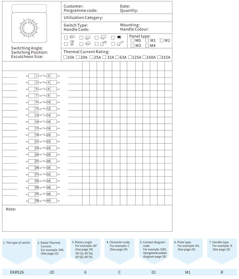
Due to the flexibility selection of EKRS series contact ratings and number of contacts etc, their combination number is almost limitless, to ensure that a right switch is chosen for the application, so -we prepare the following Customized programme Form for our customers order special switches. Only EKRS26 series.