What Technical Parameters Define Reliable Electrical Protection Devices
When you're specifying electrical protection devices, whether for a factory floor, a data center, or a commercial building, you're not just buying a component—you're purchasing peace of mind. The core question isn't simply "what device do I need?" but rather "what makes a protective device truly reliable and suitable for my specific application?" The answer lies in a set of critical technical parameters. Reliable electrical protection is defined by quantifiable metrics: Interrupting Rating, Time-Current Characteristics (TCC), withstand ratings, and selective coordination. Mastering these parameters ensures your electrical system is safe, resilient, and efficient.
Circuit Protection Fundamentals: More Than Just a Switch
Let's start by demystifying what these devices do. At their heart, circuit breakers, fuses, surge protectors, and protective relays are the guardians of your electrical network. Their job isn't to prevent faults—those are inevitable due to insulation failure, accidental shorts, or lightning strikes. Their mission is to manage a fault safely and predictably. A reliable protection device must perform two non-negotiable functions: first, it must detect an abnormal condition accurately (is it a dangerous overcurrent or just a harmless motor startup inrush?). Second, it must act decisively to isolate the problem before it escalates into fire, equipment damage, or downtime.
I’ve always viewed this as a triage system. A sensitive, fast-acting device is like an expert paramedic on site, dealing with a critical injury immediately. A slower, bulkier system is the hospital further away. The art of electrical system protection is placing the right medic at the right point in the system. This brings us to the first concrete parameter that separates a robust guardian from a weak link.
Interrupting Capacity and Withstand Capability
Imagine a dam holding back a reservoir. Its strength isn't tested on a calm day but during a historic flood. Similarly, an overcurrent protective device’s true mettle is tested during a worst-case short circuit. This is defined by its Interrupting Rating (IR) or Breaking Capacity—the maximum fault current level the device can safely interrupt without catastrophically failing.
This isn't a theoretical number. In a modern facility near utility transformers, available fault currents can exceed 100,000 Amperes. Installing a circuit breaker with a 10kA IR in such a location is a recipe for disaster. I recall an audit at a packaging plant where we found precisely this mismatch. The potential energy during a fault could have turned the breaker into an explosive hazard. The fix was upgrading to Etek’s EPB Series breakers with a 200kA IR, a specification chosen after a detailed short-circuit analysis.
Closely related is the Withstand Rating (or Icw). This is the device’s "hold-on" strength—the current it can withstand for a short duration (typically 1 second) without damage. This is crucial for coordination, allowing a downstream device time to clear a fault first. Think of it as the device's composure under extreme stress. Etek designs its protective devices with generous margins between their IR and withstand ratings, ensuring they don't just interrupt safely but also endure stressful transients without degradation.
Time-Current Characteristic (TCC) Curves
If interrupting rating is about brute strength, the Time-Current Characteristic (TCC) curve is about intelligence and precision. This graph is the fingerprint of a protective device, plotting the time it takes to operate against the magnitude of overcurrent. It’s the single most important tool for engineers.
The curve has distinct zones. For a thermal-magnetic breaker, the long-time delay region handles modest, sustained overloads (like a overloaded power strip), while the instantaneous trip region reacts violently to a dead short. The magic lies in the shape. A selective coordination study involves layering the TCC curves of all upstream and downstream devices to ensure only the device closest to a fault trips, minimizing outage impact. It's a visual symphony of curves that must not overlap at fault values.
Etek provides meticulously calibrated and digitally accessible TCC curves for all its devices. In one project for a hospital’s essential power system, we spent hours with Etek’s engineering team, digitally modeling their Molded Case Circuit Breakers (MCCBs) TCCs against feeder breakers. The goal was absolute coordination: a fault in a single patient room should not take out an entire wing’s power. The precision of their curves made this life-safety design achievable.
The Key Role of Protective Relays
For complex or high-value systems like generators, motors, or entire substations, a simple breaker isn't enough. Enter the protective relay—the supercomputer of system protection. These digital devices don’t just measure current; they analyze voltage, frequency, phase angle, and harmonics.
Their reliability is defined by a different set of parameters: Accuracy Class (e.g., 1% error margin), Operating Time (in milliseconds), and a suite of protection functions (overcurrent, differential, earth fault). A motor protection relay from Etek, for instance, can be programmed with a custom I²t curve that perfectly mimics the motor's thermal capacity, preventing nuisance trips during legitimate startups while providing ironclad overload protection. This level of customization, where device parameters align perfectly with protected equipment characteristics, is where true reliability is engineered.
The Leading Edge of Surge Protection
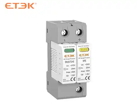
In our digital age, a different kind of threat is constant: transient overvoltages from lightning or switching. For surge protective devices (SPDs), key parameters are Voltage Protection Level (Up), Nominal Discharge Current (In), and Energy Absorption.
The Clamping Voltage is the most practical. It's the voltage at which the SPD activates to divert surge energy to ground. A lower clamping voltage (e.g., 1.2kV) offers better protection for sensitive electronics than a higher one (e.g., 2.5kV). But there's a trade-off with service life. Etek’s surge protection solutions are brilliant in their layered approach: a Type 1 device at the service entrance with a high energy rating to take the lightning bolt’s main hit, followed by Type 2 and 3 devices downstream with progressively lower clamping voltages, creating a defensive "funnel" that progressively squashes the surge.
The Necessity of Application and Coordination
Here’s my firmest opinion: a device’s standalone parameters are meaningless without application context. The "best" circuit breaker on paper can be the wrong choice for your specific electrical system. Reliability emerges from the system, not just the component.
This is where selective coordination and arc flash mitigation become paramount. Using TCC curves and software, we model fault scenarios to ensure protective devices operate in a logical sequence. The goal is to isolate the fault at the lowest possible level, preserving power elsewhere and, critically, reducing Arc Flash Energy. A well-coordinated system, using devices with fast, predictable clearing times, can lower the incident energy below hazardous levels, directly protecting maintenance personnel. Etek’s technical support excels here, helping clients not just select products but engineer safer systems.
The Perfect Blend of Specifications and Customization
Many manufacturers sell boxes with data sheets. The leading ones, like Etek, sell solutions backed by engineering partnership. What I’ve consistently appreciated is their willingness to dive into the gritty details of a project.
Facing a unique challenge with harmonic-rich currents from variable frequency drives (VFDs) in a water treatment plant? Standard thermal trips can be unreliable. Etek’s team can specify their electronic trip units with filters tuned to ignore the harmonic content, focusing only on the fundamental 50/60Hz current that indicates a true overload. This isn't off-the-shelf; it’s application-engineered protection.
Their customization service extends to physical attributes, branding, and communication protocols (like supporting both Modbus and Profinet in the same relay family). This flexibility ensures their protective devices don’t just meet the technical parameters but integrate seamlessly into your existing control and monitoring landscape.
The Perfect Blend of Specifications and Customization
So, how do you, as a buyer or specifier, action this knowledge?
-
Know Your System: Obtain or calculate your available short-circuit current at key points.
-
Define the “Why”: Is the goal pure equipment protection, life safety, continuity of service, or all three? This prioritizes parameters.
-
Demand Transparency: Insist on clear, tested TCC curves and interrupting ratings from suppliers.
-
Think in Systems, Not Devices: Plan for coordination and future expandability.
-
Partner, Don’t Just Purchase: Choose a brand like Etek that offers pre-sales engineering support to model your system’s behavior.
The most reliable electrical protection scheme is a balanced blend of rigorously applied technical parameters, deep system understanding, and products built with consistent quality. It transforms your electrical infrastructure from a vulnerable utility into a predictable, manageable, and safe asset.
.webp)