Model:
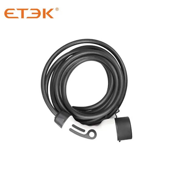
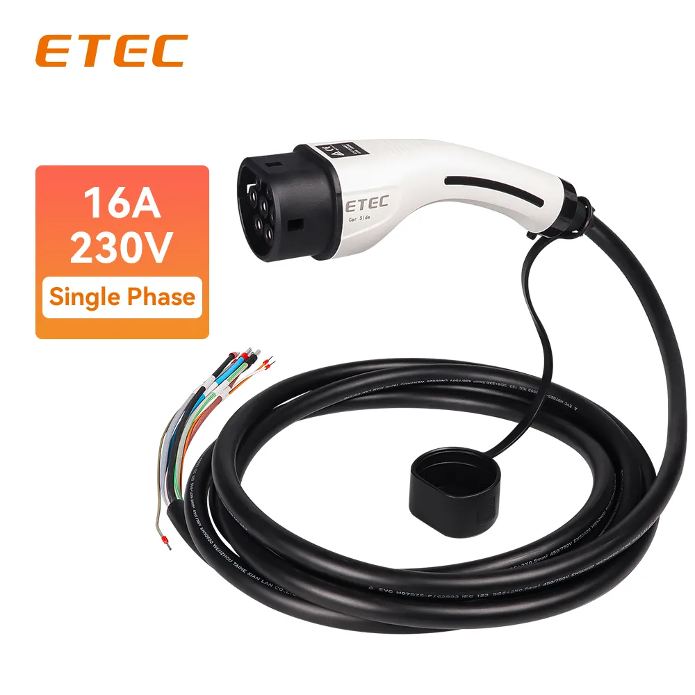
ETEC EKEP1-T2-16 Female Type 2 AC Charging Plug Single Phase 16A 3.7KW 230V with 5 Meters Cable for electric car end
Inquire

● Compliant with IEC 61851-1 standard (mode 3 charging)
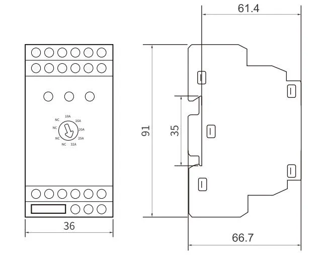
● Modular design, rail installation
● Adjustable charging current (maximum 32A)
● Support Modbus-RTU protocol and RS485 communication method
● Configurable master and slave devices
● Equipped with dynamic load balancing management (DLB) function
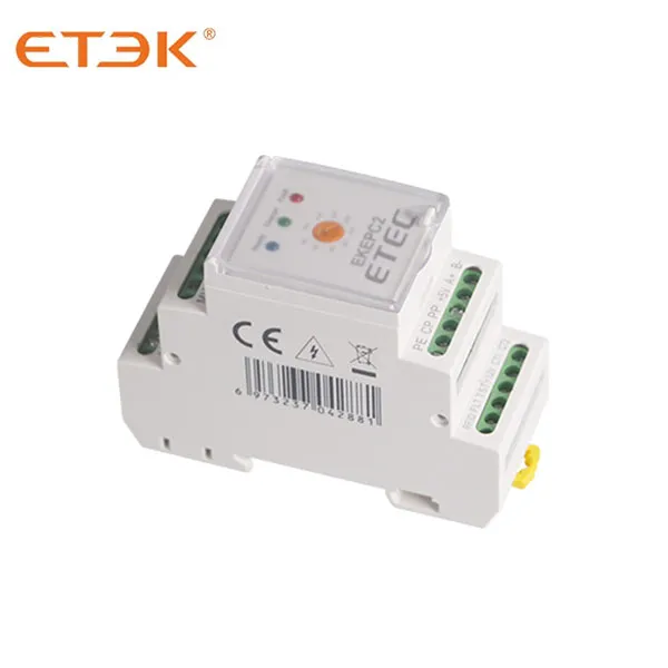
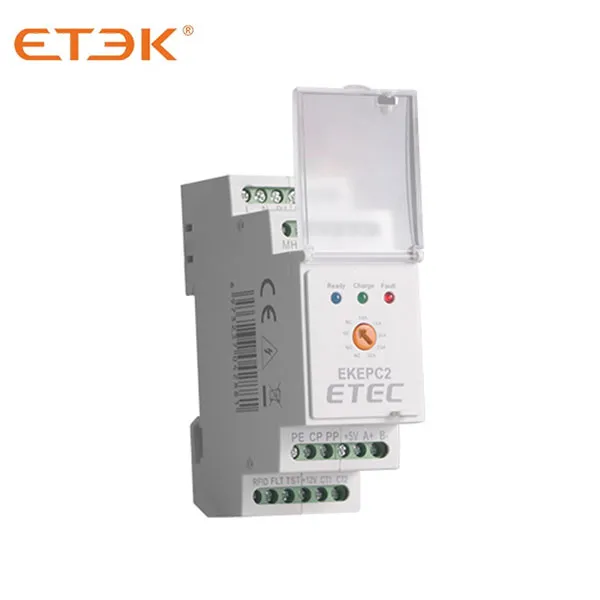
EKEPC2 is an AC charging pile controller designed for DIN rail installation. As the core intelligent control component of the AC charging pile, it complies with the IEC61851-1 or GB18487.1-2015 standards and can achieve outstanding performance of up to 32A charging current in mode 3.
EKEPC2 supports Modbus-RTU protocol and RS485 communication, has highly flexible expansion capabilities, and is compatible with a variety of devices, including but not limited to contactless IC cards, residual current detection devices (RCMU), DLB current detection devices, LCD displays, energy meters, electromagnetic locks, and external emergency stop buttons. Together, these devices enable the diverse functions of the charging pile, including DLB (dynamic load balancing) and PEN fault protection.
These features provide charging pile manufacturers and installers with a cost-effective solution that can meet charging needs in different application scenarios.
High Power Charging: Supports AC charging up to 22kW, ensuring rapid and efficient charging for a wide range of electric vehicles.
Type 2 Socket Support: Engineered for charging stations equipped with Type 2 sockets, the most prevalent standard in Europe and many other regions worldwide.
Intelligent Charging: Features advanced load balancing capabilities to optimize power distribution and prevent grid overload.
Secure Authentication: Supports RFID card reader integration for reliable user authentication and access control.
Versatile Connectivity: Support Modbus-RTU protocol and RS485 communication method for robust communication with backend systems.
Space-Efficient Design: Compact construction allows for easy integration into various charging station designs.
Durable Construction: Built to withstand diverse environmental conditions, ensuring long-term reliability in outdoor installations.
Safety Compliant: Meets relevant IEC standards for EV charging equipment, guaranteeing safe and reliable operation.
Residential EV charging stations
Workplace charging solutions
Public parking facilities
Commercial and retail locations
Fleet charging depots
Hospitality sector (hotels, restaurants)
Multi-unit residential buildings
The EKEPC2 AC Charging Station Controller represents ETEK Electric's commitment to advancing EV charging technology. By selecting this controller for your charging stations, you're investing in a smart, efficient, and future-ready solution that caters to the evolving needs of electric vehicle users and charging station operators alike.
Its combination of high power capability, intelligent features, and industry-standard compliance makes the EKEPC2 an excellent choice for businesses and individuals looking to establish reliable and user-friendly EV charging infrastructure.
Contact ETEK Electric today to learn more about how the EKEPC2 AC Charging Station Controller can elevate your EV charging solutions and contribute to the growth of sustainable transportation infrastructure.
| Model | EKEPC2-C(Socket type) | EKEPC2-S(Cable type) |
| Operating voltage | 230V±10% | |
| Auxiliary output voltage | DC12V/100mA,DC5V/100mA | |
| Charging mode | Mode 3 according to IEC61851-1 via IEC62196-2 or SAE J1172 (socket or tethered cable outlets) |
|
| Charging Current | 16A(6-8-13-16A, Adjustable) | |
| 32A(10-16-20-25-32A, Adjustable) | ||
| 63A(Customized) | ||
| Basic functions | Over-temperature protection | |
| Additional Functions and Compatible Devices | DC leakage current detection (≥6mA), requires external RCMU | |
| RFID start-stop function, requires an RFID card and an external card reader | ||
| LED charging status display and LCD screen display, external LED lights and LCD screen are required. | ||
| Solenoid interlock for socket | ||
| DLB requires an external 100A/5A ratio CT or MID meter. | ||
| Real-time monitoring of voltage, current, and power requires an external 100A/5A ratio CT and MID-certified meter. | ||
| PEN fault protection, external SPD is required | ||
| Emergency stop function requires an external emergency stop button switch. | ||
| Over-voltage, under-voltage, and over-current protection settings need to be configured in the software background. | ||
| Communication protocol | Modbus-RTU protocol and RS485 communication mode | |
| Operating temperature | -25 °C to 50 °C | |
| Relative humidity | 5%~95% | |
| Altitude | ≤2000m | |
| Protection grade | IP22 | |
| Cooling method | Natural cooling | |
| Mounting | DIN Rail (35mm) | |
| Terminal | Description |
| L | Connects to AC “live” or “line” with 230V±10%@50Hz |
| N | Connects to AC“neutral”line with 230V±10%@50Hz |
| P1 | Connect to contactor coil A1 |
| P2 | Connect to contactor coil A2 |
| FB | Feedback signal of solenoid interlock. If lock feedback is selected, the lock feedback of solenoid |
| FB (0V) | interlock is read. |
| MH | Provides a drive current to continuously energize the solenoid interlock. |
| Provides a drive current to change the motorized interlock state to locked, the signal is activated for 500ms and changes to pulse 500ms intervals until the lock is closed. | |
| Rating 12V 300mA. | |
| ML | Provides a return path for the solenoid interlock drive current ML. |
| Provides a drive current to change the motorized interlock state to unlocked. | |
| Rating 12V 300mA. | |
| 0V | 0V connection terminal for RCMU and IC card circuit |
| RED | Connected to the red indicator light, rating 5V 10mA |
| GRE | Connected to the green indicator light, rating 5V 10mA |
| BLU | Connected to the blue indicator light, rating 5V 10mA |
| IC | Connect the input signal of the IC card control to the TTL level signal (DC 3.3V/5V), and connect the other side to the 0V terminal. |
| FLT | Connect to the RCMU "Fault Out" to read the fault signal from the RCMU. |
| TST | Connect to the RCMU "Test". The controller sends a test signal to the RCMU before each charging to detect whether the RCMU is working normally. |
| +12V | 12V power supply, Rating DC+12V, 100mA |
| CT1 | Connect to the main circuit CT1. When the controller turns on the DLB function, it is necessary to connect the main circuit CT signal (signal: AC0-5A). |
| CT2 | Connect to the other side of the main circuit, CT1. |
| PE | Power ground terminal |
| CP | Control Pin. Connects to the CP of IEC61851/J1772 EVSE socket/plug. |
| PP | Proximity Pin. Connects to the PP of IEC61851 EVSE socket. |
| +5V | Power supply, Rating DC+5V,100mA |
| A+ | They are connected to the A+ and B- ports of RS485 communication respectively and can communicate with RS485 devices. The communication standard complies with the Modbus-RTU mode, baud rate: 38400, n,8.1, and the default address number is: 01H. |
| B- |
To cater to the DIY needs of users, this controller features an integrated DIP switch on the PCB board (the controller cover needs to be removed), which allows users with a certain level of electrical knowledge to more easily implement various additional functions.
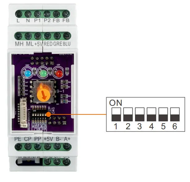
| Switch position | No. | Description |
| ON | 1 | Socket version working mode |
| 2 | Add RCMU module function | |
| 3 | Enable IC card working mode | |
| 4 | Enable solenoid interlock function | |
| 5 | Enable DLB current balancing working mode | |
| 6 | Externally connectable LCD display | |
| OFF | 1 | Cable version working mode |
| 2 | No RCMU module function | |
| 3 | Disable IC card working mode (enabled when card is lost) | |
| 4 | Disable solenoid interlock function | |
| 5 | Default working mode | |
| 6 | Externally unconnectable LCD display |