 United States (English)
 Russia (Pусский)
 France (Français)
 China (中文)
 Spain (Español)
 Germany (Deutsch)
 Portugal (Português)
 Slovakia (slovenský jazyk)
 Australia (English)
 New Zealand (English)

Application of Impulse Relays for Staircase Lighting in Multi‑Story Buildings
In office towers and multi‑story apartment buildings, staircase lighting is often overlooked—yet it represents a significant source of wasted energy. Leaving corridor lights on 24/7 is no longer acceptable under modern energy codes; conversely, relying on standalone motion sensors at every landing drives up both equipment costs and nuisance triggering.
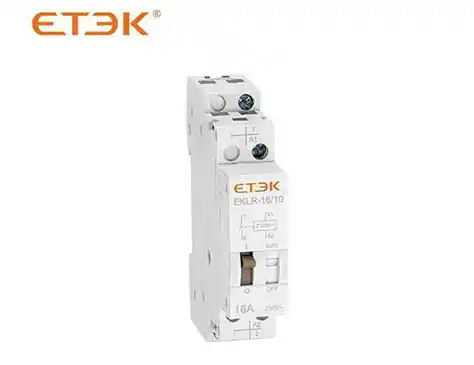
Impulse relays—also known as latching relays or bistable relays—offer a proven, economical, and highly reliable alternative. With a simple momentary push button on each floor, a single impulse relay controls the entire staircase lighting loop, slashing wiring complexity, eliminating standby power consumption, and seamlessly integrating timer‑based auto‑off functions.
What Is an Impulse Relay – The Latching Principle
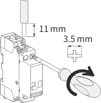
Unlike conventional contactors or general‑purpose relays, an impulse relay changes its contact state (open ↔ closed) upon receipt of a short electrical pulse—typically 50 ms to 100 ms—and mechanically latches in that position without any further coil energisation.
-
Coil energisation only during switching – The coil draws current for a fraction of a second when a push button is pressed. Once the armature moves, a permanent‑magnet or spring‑loaded mechanical latch holds the contacts firmly.
-
Zero holding power – In the latched state, the coil is completely de‑energised. No heat is generated, and no standby energy is consumed—critical for green building certifications.
-
Two stable positions – Bistable impulse relays remain in their last commanded state even after a complete mains power outage, enhancing safety and occupant convenience.
This principle makes impulse relays inherently superior to ordinary contactors for intermittent lighting applications: there is no humming, no coil heating, and no need for bulky heat dissipation.
Typical Staircase Lighting Circuit with an Impulse Relay
A standard staircase installation uses just one impulse relay to govern the entire lighting circuit for a given stairwell, regardless of building height.
Basic components:
-
One impulse relay installed in the main distribution board.
-
Multiple momentary push button switches (normally open, spring‑return) mounted at each floor landing, stair entrance, or intermediate landing.
-
Lighting luminaires connected to the relay output.
Operation:
-
First press – An occupant presses any push button. The impulse relay receives a pulse, closes its main contacts, and turns on the staircase lights.
-
Second press – The same or any other button sends another pulse, causing the relay to open its contacts and switch the lights off.
-
Timer‑assisted auto‑off – In modern impulse relays with built‑in timers, the first press also starts a countdown. At timer expiry, the relay automatically resets to the OFF state—unless a new button press resets the timer.
All push buttons are wired in parallel on a two‑wire signal bus, meaning that pressing any button generates the same pulse at the relay coil. This parallel topology is the key to the system’s wiring efficiency.
Wiring Topology – Savings Compared to Conventional Methods
Conventional approach:
-
Every light fixture or group of fixtures requires its own switch wire back to each control point.
-
For a 10‑story building with 3 control points per floor, the cabling quickly escalates to hundreds of metres of 3‑core+earth cables, with complex intermediate switching arrangements.
-
High labour cost for termination and troubleshooting.
Impulse relay solution:
-
From distribution board to relay – One dedicated supply cable to feed the relay coil and the lighting circuit.
-
From relay to push buttons – A single, daisy‑chained two‑wire signal pair running vertically through the stairwell. All buttons connect in parallel to this pair.
-
From relay to luminaires – One switched live output that branches to all lighting points.
Quantified benefit: Copper cable usage is reduced by 60 % or more compared to conventional multi‑way switching. For a 15‑story residential tower, this translates to direct material savings of several thousand dollars, plus significantly lower installation labour.
Timer Functionality – Auto Off After a Set Period
The majority of modern impulse relays designed for staircase lighting incorporate an adjustable off‑delay timer.
How it works in practice:
-
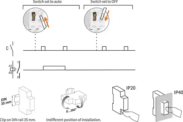
Press any push button → relay latches ON and lights turn on; the internal timer simultaneously starts counting down.
-
If the timer reaches zero without further intervention, the relay automatically unlatches, extinguishing the lights.
-
Re‑triggering behaviour: Pressing any button while the lights are already on resets the timer to its full setting. This feature is invaluable for users who need extended illumination while carrying loads or cleaning.
Configuration tip: For staircases with low pedestrian traffic, set the timer to 60 seconds. For hospital or elderly care facilities, choose 3–5 minutes. Most relays offer DIP‑switch or potentiometer adjustment, and some advanced models allow external potentiometer remote adjustment.
Selection Parameters for Staircase Lighting
When specifying an impulse relay for a stairwell project, focus on the following parameters:
| Parameter | Recommended Value / Consideration |
|---|---|
| Rated current | 16 A is sufficient for up to 100 modern LED luminaires. |
| Coil voltage | 24 V DC is strongly recommended. It is SELV, allowing push buttons to be mounted on metal switch plates without earth‑leakage concerns. It also eliminates shock hazards during maintenance. 230 V AC coils are possible but require insulated buttons and separate compartmentalisation. |
| Minimum pulse duration | Look for ≤ 50 ms. This ensures reliable operation with standard momentary switches, even when pressed briefly or with worn contacts. |
| Number of output contacts | 1 NO for a single lighting circuit; 2 NO if you need to split the staircase into odd/even floor groups. |
| Timer range | Choose a model with a range that matches your traffic patterns—typical options: 0.5 min to 20 min. |
| Mechanical life | ≥ 1 × 10⁶ operations. |
Additionally, verify that the relay’s output contacts are suitable for LED loads—some older models have minimum switching current requirements that may not be met by very low‑power LEDs. Choose relays with zero‑cross or micro‑load capability if necessary.
Avoiding Common Wiring Mistakes
Despite the simplicity of impulse relay circuits, several pitfalls regularly appear on site:
Mixing different control voltages on the same push‑button bus
-
Example: buttons on the ground floor powered from a 24 V DC supply, while buttons on the upper floors connected to a separate 230 V AC source—all paralleled together.
-
Consequence: The 230 V feeds back into the 24 V coil, instantly destroying the relay coil and potentially damaging the power supply.
-
Solution: Use a single, common control voltage for all push buttons. For 24 V DC systems, ensure every button is rated for DC use and wired back to the same SELV supply.
Using illuminated push buttons
-
The indicator lamp creates a permanent bypass path across the push‑button contacts.
-
Consequence: The relay coil may see a continuous low‑level current, causing it to oscillate or stay permanently energised—overheating and premature failure.
-
Solution: If pilot indication is required, use a separate LED indicator wired in parallel with the lighting circuit output, not across the button contacts. Alternatively, choose relays with a dedicated pilot‑light terminal that uses a separate contact.
Paralleling multiple impulse relays to control the same lighting load
-
Some installers attempt to add redundancy by connecting two relays in parallel.
-
Consequence: The relays will inevitably lose synchronisation after a few presses, causing the lights to flicker or remain stuck.
-
Solution: Use a single, correctly sized impulse relay. For redundancy, install a changeover switch to select between a primary and backup relay—never parallel their outputs directly.
Integration with Building Automation Systems
For projects requiring central monitoring or interfacing with a Building Management System (BMS), select an impulse relay equipped with auxiliary contacts.
Typical BAS integration:
-
The auxiliary contact mirrors the main contact status: closed when lights are ON, open when OFF.
-
This dry‑contact signal is fed to a digital input on the BAS controller, providing real‑time status feedback for energy dashboards or fault alarms.
-
Advanced feature – forced‑ON override: Many relays offer a separate “override” terminal. When energised, it forces the relay into the ON state regardless of timer or push‑button commands. This is essential for firefighter‑controlled evacuation lighting and complies with EN 54 or local fire codes.
Communication options: Some high‑end impulse relays now include KNX, Modbus, or DALI interfaces, enabling central scheduling, remote on/off, and integration with occupancy‑prediction algorithms.
Frequently Asked Questions
Q: What is the lifespan of an impulse relay?
A: The mechanical endurance of quality impulse relays is rated at 1 × 10⁶ operations. To put that in perspective: 100 operations per day equals 36,500 operations per year, yielding over 27 years of service life. Electrical endurance depends on the switched load—resistive LED loads often reach 1 × 10⁵ operations or more.
Q: Can I use a normal contactor instead?
A: Yes, but it is not recommended. A standard contactor requires continuous coil energisation to maintain the closed state, resulting in:
-
Constant power consumption.
-
Coil heating, shortening insulation life.
-
Acoustic humming.
For intermittent lighting, the impulse relay is the correct, energy‑efficient choice.
Q: Do impulse relays work with emergency lighting?
A: Yes, but with an important distinction: latching relays retain their state during a power outage—so if the lights were ON before a mains failure, they will remain ON when power is restored. For fire‑rated emergency escape lighting, consult local codes: some jurisdictions require designated emergency luminaires to remain permanently ON, independent of the impulse relay. In such cases, use the relay only for non‑emergency “comfort” lighting and keep separate emergency circuits.
Q: How many push buttons can be connected in parallel?
A: Theoretically, there is no strict limit. In practice, long cable runs introduce capacitance, which can cause phantom pulses due to capacitive coupling. For runs exceeding 200 m total length or more than 50 buttons, it is prudent to:
-
Use a low‑capacitance twisted‑pair cable.
-
Add a series resistor at each button to dampen transients.
-
For very large installations, deploy a decentralised approach with a separate impulse relay per floor and a central master relay—or use an interface relay to buffer the pulse.
Summary – Three Reasons to Choose Impulse Relay for Staircases
-
Significant material & labour savings – The parallel push‑button wiring reduces copper consumption by over 60 % compared to conventional multi‑way switching, with fewer junction boxes and shorter installation times.
-
Zero standby energy consumption – The latching mechanism means the coil draws current only for milliseconds during switching. No heat, no wasted energy—contributing to low‑carbon building targets and reduced electricity bills.
-
Effortless expandability – Adding a new floor or an intermediate landing is as simple as running a two‑wire pair to a new push button and connecting it in parallel. No need to re‑engineer the entire control logic or upsize contactors.
By combining the latching relay principle with an adjustable off‑delay timer and simple parallel wiring, impulse relays deliver a robust, low‑cost, and future‑proof solution for multi‑story staircase lighting. Whether you are retrofitting an existing building or designing a new installation, this application merits serious consideration—and has been proven in millions of installations worldwide.
Disclaimer: Always consult your local electrical codes and standards. Sizing and selection should be performed by a qualified electrical engineer based on actual load calculations and site conditions. All brand names and product references are for illustrative purposes only.