 United States (English)
 Russia (Pусский)
 France (Français)
 China (中文)
 Spain (Español)
 Germany (Deutsch)
 Portugal (Português)
 Slovakia (slovenský jazyk)
 Australia (English)
 New Zealand (English)

Distribution Box Layout Best Practices for Industrial Panels
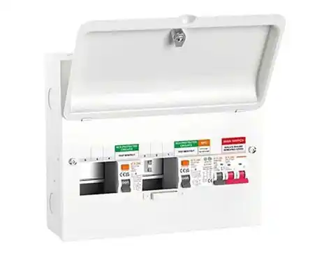
A messy distribution box is more than an eyesore – it becomes a real obstacle during fault‑finding and can significantly shorten the service life of expensive components due to trapped heat. For panel builders and in‑house automation teams, a well‑planned layout directly affects commissioning time, maintenance costs, and long‑term system reliability. This guide collects proven field practices and relevant standards to help you design distribution boxes that are safe, easy to service, and ready for future modifications.For a full range of low‑voltage electrical components that support these layout practices, you can explore the product offerings from ETEK Electric.
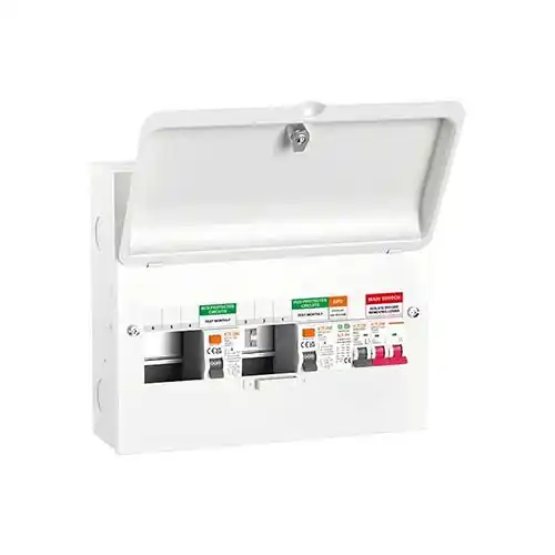
Segregate by Voltage and Function
The single most important rule in any panel layout is to keep AC power circuits physically separated from DC control circuits. Mixing 220V or 380V power with 24V control wiring invites electromagnetic interference, creates unnecessary safety risks, and makes troubleshooting confusing. A physical barrier between these zones is strongly recommended, and you should maintain at least 50 millimetres of clear space between them. This separation not only reduces noise coupling but also gives technicians a clear visual cue when working inside the panel.
Typical grouping looks like this:
-
Power section: main switch, surge protective devices (SPD), miniature circuit breakers (MCB), and contactors.
-
Control section: relays, PLCs, and terminal blocks for signal wiring.
Keeping these two groups on opposite sides of the enclosure or on separate mounting plates simplifies wiring and reduces the chance of accidental contact with live parts. To learn more about ETEK's company background and manufacturing capabilities, visit their about page.
Arrange the DIN Rail in a Logical Power Flow
The 35‑millimetre DIN rail is the backbone of most industrial panels, and the order in which you mount devices should follow the natural path of power from the incoming supply to the final loads. Starting from the input side, the sequence typically runs as follows:
-
Incoming terminal block
-
Main isolator or switch‑disconnector
-
Surge protective device with its own backup MCB
-
Main residual current device if required
-
Branch MCBs for each outgoing circuit
-
Contactors or relays for circuits that need switching control
-
Output terminal blocks for load connections
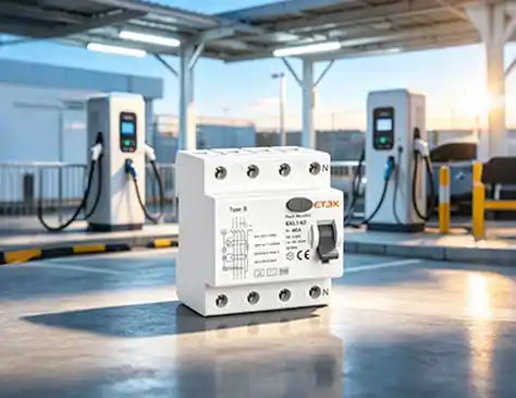
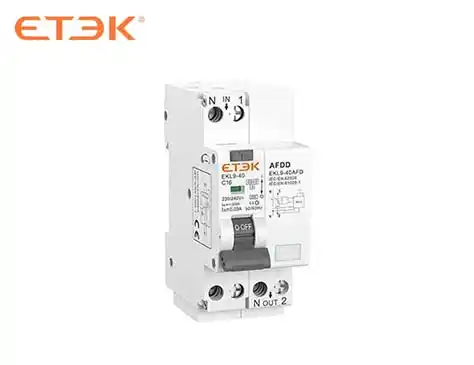
You should mount all rails horizontally and fit end stops to prevent components from sliding loose under vibration. Keeping each functional group on a separate rail makes the layout more intuitive and reduces the chance of wiring errors. Remember that the physical arrangement should mirror the electrical schematic as closely as possible, so that anyone reading the diagram can easily locate each component in the box. ETEK offers a comprehensive product portfolio covering MCB, RCCB, RCBO, AFDD, contactors, SPD, and many other modular devices that fit standard DIN rail installations.
Give Heat‑Generating Components Enough Breathing Space
Heat is one of the biggest enemies of electrical components, and it tends to rise and accumulate around contactors, power supplies, and transformers. If you pack these devices too tightly, the internal temperature of the enclosure can rise well above safe limits, leading to premature failure or nuisance tripping. As a general rule, you should respect these minimum clearances:
-
At least 20–30 mm between adjacent active devices.
-
At least 30 mm vertical clearance above contactors, because heat rises and can affect components mounted higher up.
-
For circuits carrying more than 100 amperes, using wider busbars helps reduce contact resistance and localised heating.
Surge protective devices should never be mounted directly next to large contactors, as the radiated heat can degrade their performance. If the enclosure’s IP rating permits, installing a ventilation fan near the top of the box can greatly improve air circulation and keep internal temperatures under control. Also, avoid blocking the ventilation slots on the enclosure – warm air must be able to escape freely. For practical insights on protecting your panel from summer thunderstorms, you may find this blog article on surge protective device prevention helpful.
Choose a Wiring Method That Favours Serviceability
There are two common approaches to routing internal wires: using slotted wiring ducts or running point‑to‑point “air” wires. Duct‑based wiring produces a neat and professional appearance, and it makes adding new circuits much easier because you can simply drop new wires into the existing raceway. For most multi‑circuit panels, this is the preferred method, provided you keep the duct fill below about 50 percent to leave room for future additions. Point‑to‑point wiring saves space and can be useful in very compact enclosures, but it becomes difficult to modify later because every wire is individually routed and often zip‑tied in place.
A sensible hybrid approach works well in practice:
-
Run power cables through the lower ducts.
-
Run signal and control cables through the upper ducts.
-
Never mix power and signal wires in the same duct to avoid electromagnetic interference.
Whichever method you choose, always ensure that internal wires terminate at the top of connectors and external field wires at the bottom, so that internal and external cables never cross each other unnecessarily. This simple rule makes tracing circuits much easier during maintenance.
Organise Terminal Blocks with Clear Labelling
Terminal blocks are the interface between your panel and the outside world, and poor organisation here can cause endless confusion. Every wire must be identified with a numbered ferrule at both ends, and the numbers must match the electrical schematic exactly. You should dedicate specific terminal strips for external cables rather than connecting field wires directly to devices, because this makes replacement and testing much simpler. It is wise to reserve about 20 percent of the terminal positions as spares, so that future sensors or actuators can be connected without having to add new strips.
Grouping terminals by function is highly recommended, for example:
-
X1 – Power input
-
X2 – Motor outputs and heavy loads
-
X3 – Control signals and instrumentation
-
X4 – Communication or fieldbus connections
Clear, durable labelling on every terminal strip is not an optional extra – it is essential for safe and efficient maintenance. Use printed marker strips rather than handwritten labels, and ensure they are resistant to moisture and abrasion.
Reserve Space for Future Expansion
Industrial panels are rarely static; new machines, extra safety devices, or upgraded controls will almost certainly require additional circuits over time. Planning for expansion from the very beginning is far cheaper than rebuilding a cramped enclosure later. To prepare for the inevitable, follow these simple reservations:
-
Leave at least five empty module positions on each end of every DIN rail.
-
Keep at least one spare four‑pole MCB slot available for a new branch circuit.
-
Leave two or three spare positions on each terminal block strip.
-
Ensure wiring ducts are no more than 50% full after initial wiring.
This forward‑thinking approach does not cost much extra in terms of enclosure size, but it saves a great deal of time and money when modifications become necessary. Think of the panel you will need five years from now, not just today.
Maintain Proper Labeling and Documentation
A beautifully wired panel becomes almost useless if no one can understand its layout without a long search. Every component should carry a numbered label that corresponds directly to the electrical diagram, and the same label should be repeated on the back panel next to the device for quick visual identification. A laminated copy of the full circuit diagram must be fixed inside the enclosure door, preferably in a waterproof plastic sleeve, so that technicians can refer to it without carrying separate prints.
The door label should also display:
-
Rated voltage of the panel.
-
Short‑circuit current rating (SCCR).
-
Maximum total load in amperes.
In addition, keeping a complete bill of materials with order numbers for every installed device makes reordering and replacement straightforward. Good documentation turns a complex assembly into a manageable and maintainable asset. Colour coding of wires is also a valuable practice that complements the labels.
Final Pre‑Assembly Checks
Before you cut any mounting holes or start fitting components, run through a few essential checks to avoid costly mistakes. Confirm the total width of all devices plus the reserved spare space does not exceed the available DIN rail length. For three‑phase systems, double‑check the phase sequence to prevent motor rotation problems. Verify that the neutral busbar and the earth busbar have enough terminals for all connections, and that the protective earth conductor is properly sized. Make sure your bill of materials is complete with correct order numbers for every part. Review the segregation between AC power and DC control zones, and ensure that all cooling clearances are respected. Finally, prepare all labelling materials – ferrules, marker strips, and the laminated diagram – so that you can apply them during assembly without interrupting the workflow. Following these simple checks will save you hours of rework and give you a distribution box that performs reliably for years.